
Contents
Introduction
Equipment used
Test procedure
Processing procedure
Results
Conclusions
Introduction
OxTS inertial navigation systems combine an IMU made up of accelerometers and gyroscopes with GNSS positioning to deliver a full 3D position, attitude, and motion solution. GNSS technology provides long term stability and absolute accuracy with the downside of requiring a clear view of multiple satellites. Inertial technology provides short term stability and performance in any environment, with the downside of integration errors building up quickly if left unchecked. By combining the two, we get the benefits of each technology while mitigating the drawbacks. The inertial measurements are aided by GNSS updates to correct the error propagation and the position solution is maintained by the inertial measurements during brief GNSS interruptions.
In some applications such as land-based mobile mapping or open-road ADAS development, GNSS interruptions and outages are unavoidable. In the worst-case scenario of a complete GNSS outage with no external aiding, the navigation solution relies on pure inertial dead reckoning. In this case, the quality of the IMU will determine how quickly the errors build up.
However, with OxTS inertial navigation systems there are some additional aiding inputs you can use to aid the inertial measurements in the absence of GNSS. These are a Wheel Speed Sensor (WSS) and Advanced Slip (AS).
A WSS, also known as a Distance Measurement Instrument (DMI) is an external sensor that can be mounted on a vehicle’s wheel to measure velocity. In the absence of GNSS, these velocity updates help constrain the drift and maintain the trajectory.
AS doesn’t require any external equipment, just a few extra measurements during set up and configuration. In a typical land vehicle like a car or van, the navigation system can make some assumptions about the motion profile and place restrictions on certain measurements. For example, cars generally can’t rotate on the spot or perform VTOL manoeuvres. These constraints stop errors in measurements like the vertical velocity from causing big jumps or drift.
We have performed some tests to evaluate the performance of OxTS inertial navigation systems in extended GNSS outages using a combination of these additional aiding inputs.
Equipment used
- RT3003
- RT1003
- RT-Base S with Satel radios
- Wheel Speed Encoder (Pegasem WSS3, 1024 PPR)
- 2x G5Ant-2AMNS1 GNSS antennas
Test procedure
Data collection for the RT3000 and RT1000 had to be done on separate occasions. The same installation and configuration procedure was performed on each occasion. Data was collected at the Upper Heyford airfield. The RT was installed rigidly in the rear of the vehicle. The RT-Base S was set up nearby to transmit differential corrections for RTK positioning. The wheel speed odometer was installed on the right rear wheel and connected to the unit. The RTs were configured with lateral and vertical Advanced Slip settings, differential corrections (RTCMv3) and Wheel Speed.
A comprehensive 15 minute warm-up was performed, then the Get Settings function was used to extract the corrected lever arms. The improved configurations were recommitted to the units. A subsequent short warm-up was performed before starting the data collection. The circuit shown in Figure 1 was driven at varying speeds for 2 hours. At the end of the test a warm-down procedure was performed to mimic the warm-up for when the data is processed in reverse.

This circuit was driven to ensure maximum diversity in the motion profile with varying speeds, a variety of straight sections, and left and right turns. A stationary period between each lap was also included.
Processing procedure
The raw data was processed multiple times with different configuration combinations. Post-processing allowed the use of controlled blanking periods to artificially block the GNSS for certain intervals, simulating a complete GNSS outage. Using the Combined post-processing mode also reduces error growth by combining a forwards and backwards process run of the data set.

In order to maximise statistical validity and minimise biases and correlations in the error growth due to trajectory dynamics, each processing configuration was processed multiple times with the blanked period at different points in the data set. This ensures that there is a sufficient sample of data points for each outage duration and that the outages have effectively randomised dynamics and trajectories to minimise any biases.
For each aiding configuration, a control run was processed with no blanking period. The data was then reprocessed with the set blanking period inserted into the run. The resulting output is compared to the control run and the maximum deviation from the reference is calculated for position, heading, roll, pitch, and velocity. This process is repeated a number of times, advancing the blanking period at set intervals throughout the data set. Averages are then calculated from the resulting sample of maximum deviations. This method is then repeated again with each of the blanking period times.
Results
Table 2 shows the RT3000 results for the averaged maximum drift from the reference for each blanking period. Table 3 shows the results for the RT1000.


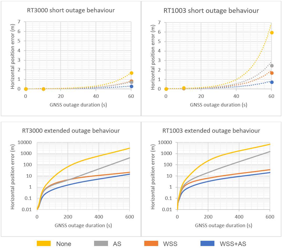
The following graphs show the horizontal position error growth over time, looking at the behaviour in short outages (up to 60 seconds) and extended outages (up to 10 minutes).
Conclusions
These results firstly show the difference in performance between the IMUs used in the RT3000 and RT1000. With the RT1000 being much smaller and a lower cost than the RT3000, the IMU is necessarily not as high quality. And as expected, the error growth is faster and larger for the RT1000.
We also see the massive improvements adding an aiding source can make over pure inertial dead reckoning. AS delivers very impressive improvements for shorter outages without the need for any external equipment, so we would highly recommend everyone using OxTS INSs on a ground vehicle to enable this setting. While AS struggles to keep up with the WSS for longer outages, it is still much better than no aiding.
If you're going to be collecting data from a ground vehicle in difficult environments and have the possibility to install a WSS on the vehicle, this will grant the greatest improvements for long outages. The direct external aiding helps the navigation system greatly in the absence of GNSS. In the future, OxTS are looking for other forms of external aiding to integrate into the navigation system using our generic aiding interface.
Comments
0 comments
Please sign in to leave a comment.